PREMIUM JET - PURE WATER CONFIGURED MODELS
Designed for Volume Production Cutting:
•
Linear Drive High Speeds exceeding 3000 ipm
•
Contour Speeds exceeding 2400 ipm
•
Multiple Carriages - software pitch distance controlled
•
Multiple Cut Head Configurations
•
Shuttle Beds - provided simultaneous loading / unloading
•
Stainless Steel Conveyor Waterjet Tables
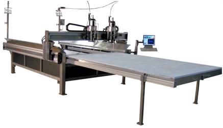
Features Specific to Pure Water Tables:
•
Gantry Spans across Narrow Table Length – Increased Acceleration.
•
Stainless Steel Catch Tank – No Standing Water.
•
Pure Water Configured Head.
•
WJ Brick Workbed – non-scratch, small part cutting platform.
•
Large Oversized Drainage - Handles Material Debris
•
High Gantry Available for 12" material cutting
Pure Water Models - PW 4 x 4 , 5 x 5, 4 x 8, 5 x 10, 6 x 12, 7 x 14, 8 x 20
Gantry - Dual X Rail Support
Picture Shown: Optional Single Shuttle Bed & Dual Powered Carriages / Cut Heads
Gantry - Dual X Rail Support
Picture Shown: Optional Single Shuttle Bed & Dual Powered Carriages / Cut Heads
Performance and Specifications
| Machine Sizes | 4 x 4 | 5 x 5 | 4 x 8 | 5 x 10 | 6 x 12 | 7 x 12 |
| Foot Print (W" x D") | 81" x 84" | 93" x 96" | 130"x 84" | 154" x 96" | 166" x 108" | 166" x 120" |
| Cut Area (W" x D") | 51" x 51" | 63" x 63" | 99" x 51" | 123" x 63" | 147" x 75" | 147" x 87" |
| Z Clearance (Standard, Optional) | 6" or 12" | 6" or 12" | 6" or 12" | 6" or 12" | 6" or 12" | 6" or 12" |
| Max Allowable Material Clearance | 8", 12" | 8", 12" | 8", 12" | 8", 12" | 8", 12" | 8", 12" |
| Machine Weight (Dry) | 2500 LBS | 2700 LBS | 2800 LBS | 3400 LBS | 3600 LBS | 3800 LBS |
| Design Features | |
| Frame Construction | Welded 3/16” Steel, optional Stainless Steel - 100% TIG Welded |
| Catch Basin | Stainless Steel - 100% TIG Welded |
| Work Bed Support | Galvanized 4” Slats ( 2.25” spacing ) optional 1.125” spacing |
| Gantry Design | Dual X Rail Design |
| Rail & Gantry Construction | Aluminum |
| Linear Ways & Guide Rollers | Stainless Steel |
| Drive Package | Linear Motor & Rare Earth Magnet Set |
| Encoder Type | Linear Magnetic Encoders - accuracy 2 microns (0.00008”) |
| Drive Amplifiers – Digital Servo | Dual X, Y |
| Z Axis Drive Package | Ball Screw – DC Motor Driven, Servo optional |
| Linear Drive Accuracy | 4 x 4 | 5 x 5 | 4 x 8 | 5 x 10 | 6 x 12 | 7 x 12 |
| Min Operating Speed (ipm) | 0.1 | 93" x 96" | 130"x 84" | 154" x 96" | 166" x 108" | 166" x 120" |
| Max Operating Speed (ipm) | 2500 | 63" x 63" | 99" x 51" | 123" x 63" | 147" x 75" | 147" x 87" |
| Max Contouring Speed (ipm) | 2400 | 6" or 12" | 6" or 12" | 6" or 12" | 6" or 12" | 6" or 12" |
| Repeatability (inches) | +/- .001 | +/- .001 | +/- .001 | +/- .001 | +/- .001 | +/- .001 |
| Backlash | +/- .0005 | +/- .0005 | +/- .0005 | +/- .0005 | +/- .0005 | +/- .0005 |
| Square | +/- .002 | +/- .002 | +/- .002 | +/- .002 | +/- .002 | +/- .002 |
| Straight | +/- .002 | +/- .002 | +/- .002 | +/- .002 | +/- .002 | +/- .002 |
| Position Accuracy in 12 inches | +/- .001 | +/- .001 | +/- .001 | +/- .001 | +/- .001 | +/- .001 |
| Position Accuracy within Cut Area ** |
+/- .002 | +/- .002 | +/- .003 | +/- .003 | +/- .0035 | +/- .0035 |
| Pure Water Cut Accuracy | +/- .002 | +/- .002 | +/- .002 | +/- .002 | +/- .002 | +/- .002 |
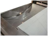
Catch Basin Design
•
Stainless Steel Catch Basin
•
Sloped for Drainage / Cleaning
•
Large Drain / Debris Opening to Weir Tank
•
Pure water cutting does not require a pool of water common to abrasive configured machines.
Adding Multiple Cut Heads
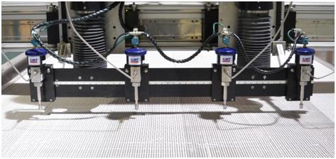
The standard machine has a single cut head assembly directly mounted to the primary linear powered carriage car. Multiple carriages can be added to the gantry Y axis as unpowered or powered. The unpowered is a slave carriage having a tie rod connection back to the primary powered carriage. The distance between the primary and slave carriage is then manually adjusted. Adding a second linear powered carriage allows each to move in sequence with pitch distance between carriages software controlled. Dual powered carriages provide best acceleration for multiple cut head configurations.
Each carriage has one cut head directly mounted or by adding a mounting plate can accommodate two cut heads per carriage. PST can assist in reviewing the cut patterns to optimize your cutting needs. Buyers of multi head machines need understand the distance adjustments between cut heads including cut envelopes for single or multi cut heads.
Each carriage has one cut head directly mounted or by adding a mounting plate can accommodate two cut heads per carriage. PST can assist in reviewing the cut patterns to optimize your cutting needs. Buyers of multi head machines need understand the distance adjustments between cut heads including cut envelopes for single or multi cut heads.
Multi Cut Head Options
| Powered Carriage |
Slave Carriage | Cut Head | Mounting | Pitch Distance Adjustment Between Cut heads |
| 1 | 1 | direct mounted to carriage | ||
| 1 | 2 | common mounting plate | Min 4"- Max 14" | |
| 1 | 1 | 2 | one cut head / carriage | 18" - 60" tie rod adjusted |
| 1 | 1 | 4 | 2 heads common mount plate / carriage | Min 6" between mount plates |
| 2 | 4 | 2 heads common mount plate / carriage | 18" - 60" software controlled |
High Gantry Option
The standard table is designed for 8 inch clearance under Gantry. Therefore operators can stack soft materials for cutting to this max height. As an option PST offers a high Gantry design yielding maximum clearance at 12 inches under Gantry. As to not induce cut head vibration this higher Gantry design reduces machine maximum cut speeds and accelerations be roughly 15%. In combination with this feature the Z Axis motion range can also be increased from 6 inch standard to 12 inches.
Park Zone Option
The optional Park Zone provides a storage location for the secondary carriage when not in use. Machines designed for multiple cut heads may have times requiring a single cut head travelling the full tables cut envelope. This feature eliminates having to remove the secondary car.
The Park Zone adds length to the Gantry to accommodate the second carriage car, therefore must be ordered at time of machine fabrication.
The Park Zone adds length to the Gantry to accommodate the second carriage car, therefore must be ordered at time of machine fabrication.
Material Handling Features
Soft materials are commonly sold in sheet form, stacked or as rolled material. These soft materials are typically light weight, flexible to handle, and in some cases will not lay flat without assistance. PST offers several material handling options to increase machine productivity. The ability to cut parts and stage materials greatly increases production capability.
Shuttle Work Bed System - optional
•
Single or Dual Shuttles Offered
•
Simultaneous Cutting while Loading
•
Manual or Auto Driven
•
Software Cut File Controlled
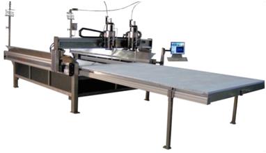
** Single Shuttle Configuration
Conveyor Belt Work Bed - optional
•
Stainless Steel Mesh Belting for Pure Water
•
Provides – Staging & Offloading Areas
•
Software Cut File Controlled
•
Auto Bite Advance
Material Hold Down Arms & Bars - optional
•
Holds material down from rolling at the edges
•
Arms at Sides & Bars at Ends
•
Pneumatic Actuated
•
Software Cut File Controlled
•
Renewable as needed
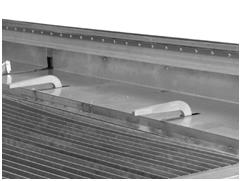
Gantry Material Clamps - optional
Pneumatically clamps grap roll stock then uses Gantry Drive to pull / advance roll stock into the Water jet cut envelope.
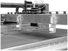
Servo Z Axis Software Controlled - optional
A “Servo Z Axis / Float” feature is optional providing software control of the cut head. The Z movements are programmed within the cut file to accommodate for materials at an angle or changes in heights.
Collision Avoidance - optional
This feature moves the cut head up after completion of each cut part prior to X or Y axis movements. This avoids possible cut head collision with completed parts that may have tipped after cutting. This feature is more common for hard material cutting and only certain cases with soft materials.
Digitizing Camera / Software - Standard Feature
All PST tables are equipped with a digitizing system consisting of software and a cutting head mounted video camera. This enables one to place a flat irregular pattern on the machine’s cut bed and trace an outline of the pattern yielding a DXF file. This file can then be input to the Post software to create a cut ready file. This system is quick and accurate enabling the user to establish cut files from odd shaped templates that would otherwise be difficult and time consuming to draw. Operator can mount camera and be ready to digitize in less than two minutes.
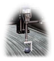
Remote Pendent Control - Standard Feature
A remote pendant is standard equipment providing the operator bidirectional motion control of the cutting head and gantry positioning. This hand held controller is ideal during material setup plus control override during cutting routines.
•
Cutting Head - up and down control ( z-axis )
•
Independent X and Y control
•
Simultaneous X and Y control – diagonal movements
•
High or Low speed switching

Download our line card
Click Shop above to browse our NEW e-commerce site
Precision Solutions for Cutting and Glass Processing Excellence
- Aculite CNC Cutting
- Glass Machinery
- Glass Processing Tables
- Auto Freefall Glass Loading
- Insulated Unit Assembly
- Automatic Applicator Table
- Tilt Top Grid Assembly Table
- Prem. Auto Seal Applicator Table
- Prem. HTT Applicator Table
- Easel Grid Table
- LKO Rotating Sealing Table
- Power Rotating Sealing Table
- Cold Single Set Roller Press
- KKO-17 Rotating Sealing Stand
- Hot Melt Clamp Table
- Desiccant Filling Machine
- Application & Hot Melt Clamp
- Glass Processing Equipment
- Glass Inspection Units
- Glass Storage Racks
- Glass Washing Equipment
- Glass Lifting Devices
- Waterjet Machinery
- Glass & Glazing Supplies
- PST Machine Parts
- Services
- Software
- Video Demos


